Raspberry Pi I2C 256K EEPROM Tutorial
I have a Bus Pirate v3 and up until now I've simply used it as a USB to Serial converter at chip signal levels. For as much as this thing can do, it's a pretty silly use for it. I figured I'd connect up an I2C EEPROM I have on hand and use it to monitor I2C communications later. I'll go over actually using the Bus Pirate to do this in a different post. For now, I'll cover actually getting the EEPROM connected up and working under Linux on a Raspberry Pi.
Make sure and have the datasheet for the Microchip 24LC256 (or whatever chip you're using). It turns out, a lot of I2C EEPROM, and even FRAM, chips have almost the same exact interface. The datasheet is needed to reference several things. Of course, the pin-out is necessary. Checking the supported bus speed of the device is a good thing to know. It's also worth knowing that the page size is 64 bytes and it can take up to 5ms to write a page according to the datasheet. If you're expecting fast write speeds, this is something to keep in mind.
Lets get to wiring. This example really can't get any simpler. My test setup involves the Raspberry Pi, a Bus Pirate connected to the Raspberry Pi serial port, and a breadboard that has the EEPROM mounted on it connected to the I2C port on the Raspberry Pi.
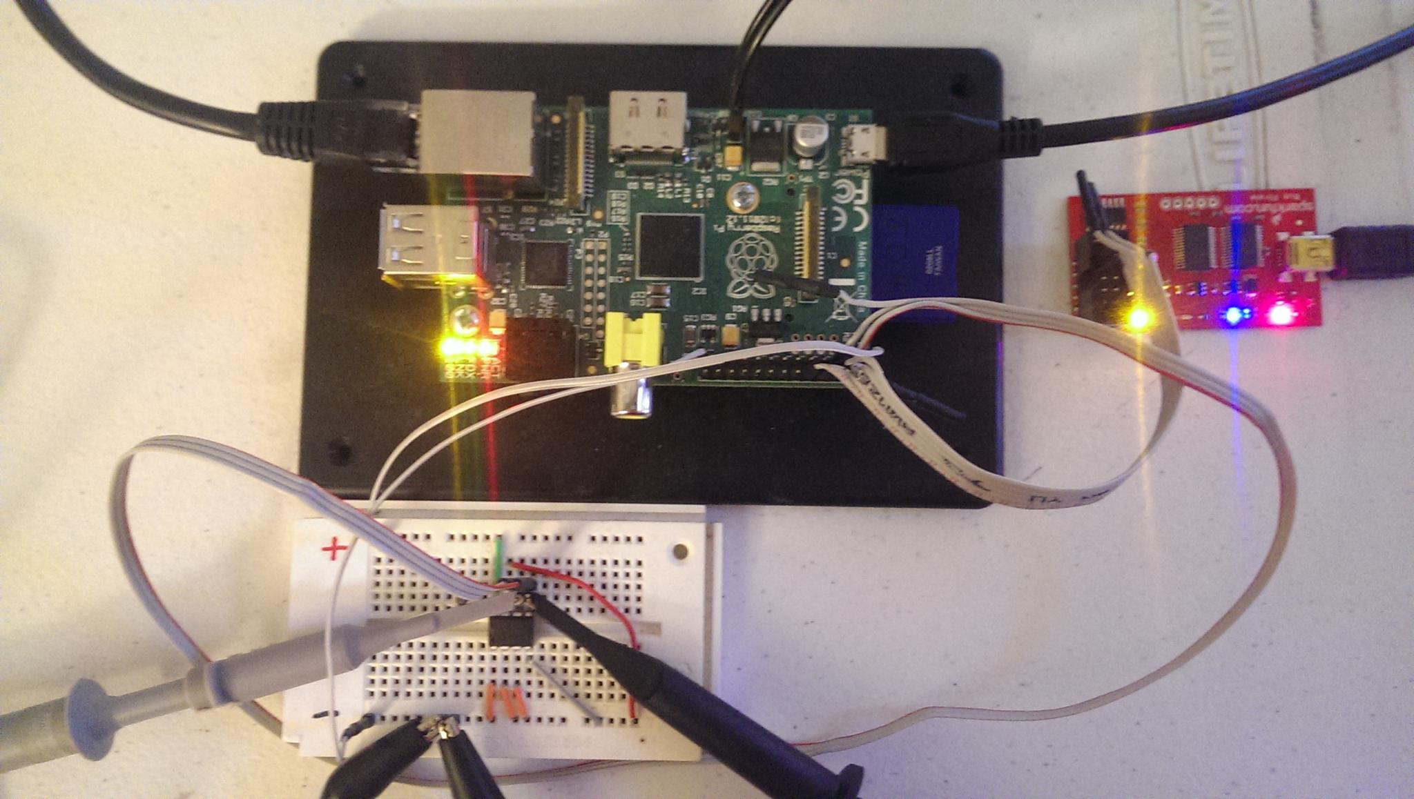
The Bus Pirate MOSI(UART Rx) and MISO(UART Tx) pins are connected to the Raspberry Pi pins 8 and 10 respectively. Also, connect up the grounds for good measure.
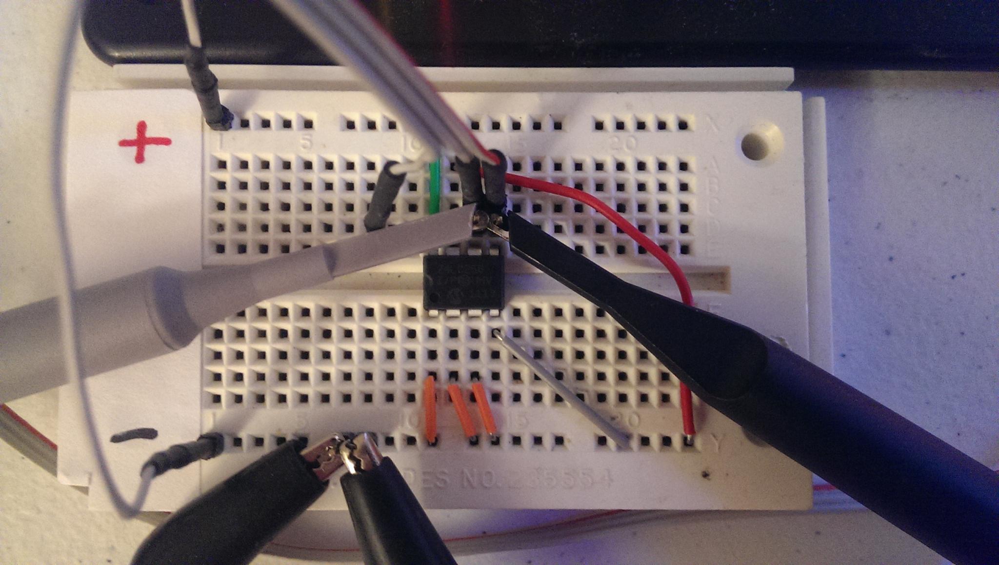
Pins 3 and 5 on the Raspberry Pi GPIO header are the SDA and SCL pins for I2C respectively (I2C is a 2 wire bus). Those get wired directly to the same pins on the chip. It turns out, these two pins have internal pullups on the Raspberry Pi. So, when they are configured for I2C, and you're not communicating, you'll see these pins high.
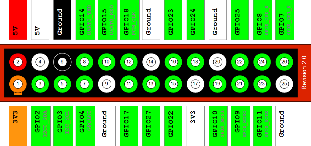
This particular chip has 3 pins used for chip select addressing. However, those 3 pins alone don't make up the address. They are part of a hard coded binary prefix of '1010'. So, if you ground the three pins, the address really becomes '1010000', which is address 0x50 in hex. It will be important to know this address later. The chip also has a write protect pin. Because I want to write to it, I need to connect that to ground according to the datasheet. Connect up the chip Vss and Vdd and that covers all 8 pins of the chip. Pretty simple.
I am using RaspberryPi-BuildRoot to create the kernel and rootfs for the Raspberry Pi. This is a version of buildroot already catered to getting a rootfs and kernel built for the Raspberry Pi quickly.
In the buildroot config, make sure and select i2c-tools to get some nifty debugging tools. You'll also need to run make linux-menuconfig and make sure the following two settings are selected. We need the at24 driver as well as the I2C bus support for the Raspberry Pi (this one should already be selected).
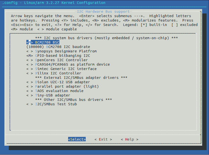
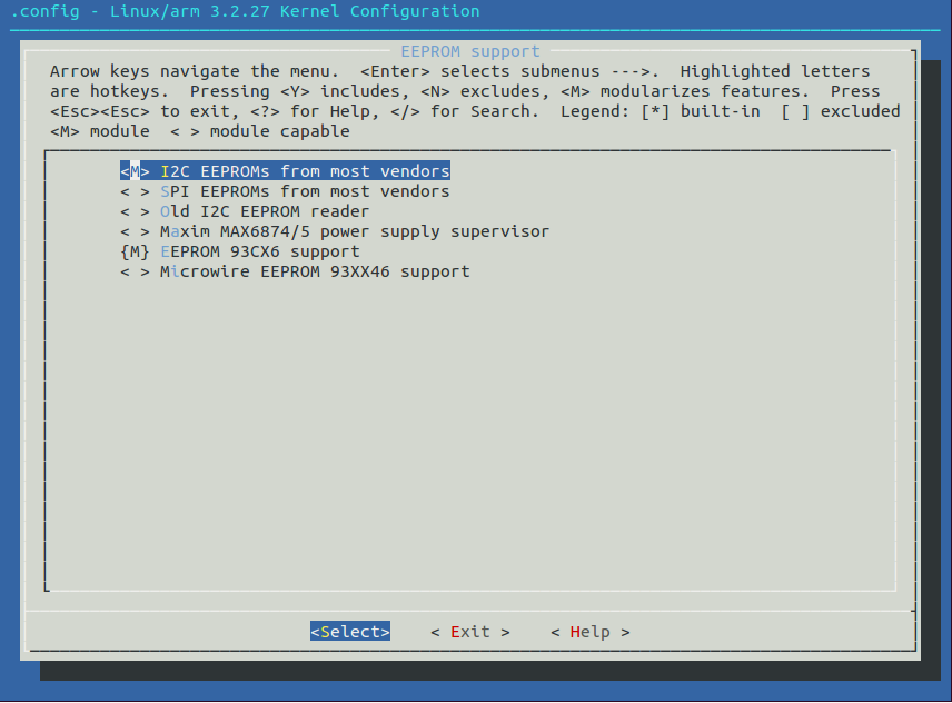
Now, here's where we need to actually write some code. The at24 driver in the Linux kernel needs some platform setup to point it to where our chip is on the I2C bus. It's worth noting that there are actually 2 I2C buses on the Raspberry Pi. The pins on the GPIO header are actually the second one, bus 1. This is the first parameter to i2c_register_board_info(). Make the following change and recompile your kernel.
--- dl/raspberrypi-linux-10182a3/arch/arm/mach-bcm2708/bcm2708.c	2012-10-15 01:54:52.000000000 -0700
+++ output/build/linux-custom/arch/arm/mach-bcm2708/bcm2708.c	2014-05-18 16:31:59.394984556 -0700
@@ -33,6 +33,7 @@
 #include <linux/module.h>
 #include <linux/spi/spi.h>
 #include <linux/w1-gpio.h>
+#include <linux/i2c/at24.h>

 #include <linux/version.h>
 #include <linux/clkdev.h>
@@ -666,6 +667,19 @@
 	arch_reset(0, "");
 }

+static struct at24_platform_data board_eeprom = {
+	.byte_len = 256 * 1024,
+	.page_size = 64,
+	.flags = AT24_FLAG_ADDR16,
+};
+
+static struct i2c_board_info rpi_i2c_devices[] = {
+	{
+		I2C_BOARD_INFO("at24", 0x50), /* E0=0, E1=0, E2=0 */
+		.platform_data = &board_eeprom,
+	},
+};
+
 void __init bcm2708_init(void)
 {
 	int i;
@@ -699,6 +713,10 @@
 	}
 	bcm_register_device(&bcm2708_usb_device);
 	bcm_register_device(&bcm2708_uart1_device);
+
+	i2c_register_board_info(1, rpi_i2c_devices,
+			ARRAY_SIZE(rpi_i2c_devices));
+
 	bcm_register_device(&bcm2708_powerman_device);
 #ifdef CONFIG_MMC_SDHCI_BCM2708
 	bcm_register_device(&bcm2708_emmc_device);
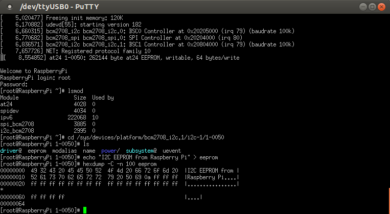
I use PuTTY (even on Linux) to access the serial console to the Raspberry Pi. Once you've got all of your wiring done and some software running, there's a quick tool from i2c-tools to test if the EEPROM is detected. Make sure the needed I2C modules are loaded. Run modprobe to insert the relevant ones missing.
[root@RaspberryPi ~]# lsmod
Module                  Size  Used by
spidev                  4034  0
ipv6                  222068  10
spi_bcm2708             3885  0
i2c_bcm2708             2995  0     <- Needed
Insert i2c-dev to use i2cdetect. You should get a 50 shown like below which means it detects a device at that address.
[root@RaspberryPi ~]# modprobe i2c-dev
[  351.754983] i2c /dev entries driver
[root@RaspberryPi ~]# i2cdetect -y 1
     0  1  2  3  4  5  6  7  8  9  a  b  c  d  e  f
00:          -- -- -- -- -- -- -- -- -- -- -- -- --
10: -- -- -- -- -- -- -- -- -- -- -- -- -- -- -- --
20: -- -- -- -- -- -- -- -- -- -- -- -- -- -- -- --
30: -- -- -- -- -- -- -- -- -- -- -- -- -- -- -- --
40: -- -- -- -- -- -- -- -- -- -- -- -- -- -- -- --
50: 50 -- -- -- -- -- -- -- -- -- -- -- -- -- -- --
60: -- -- -- -- -- -- -- -- -- -- -- -- -- -- -- --
70: -- -- -- -- -- -- -- --
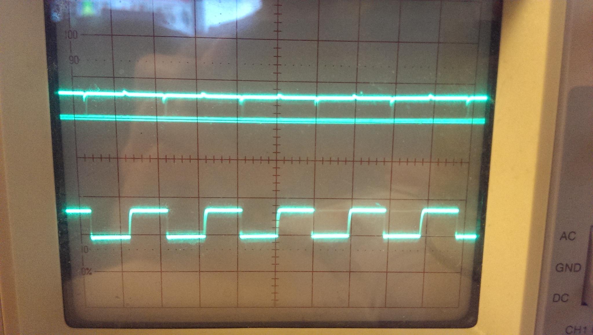
If you have an oscilloscope on hand, you can make sure the I2C port is working by generating some communications with the chip (like running i2cdetect in a loop) and connecting a channel up to the SCL pin and making sure it looks something like what's shown on the bottom here:
Now, you can follow this screenshot to actually demonstrate writing to the chip and then reading it back in, assuming everything is working as expected. A simple echo and hexdump from the sysfs eeprom file created by the at24 driver is enough for demo purposes. You can even reboot the Raspberry Pi and then re-read the EEPROM chip to make sure it was stored.
