Simple Relay Circuit and PCB
If you're looking for a way to connect up a relay to your Raspberry Pi, or Arduino, or whatever else- you probably already know that a mechanical relay usually draws far too much current for the output pins on those chips. To get around this problem, you can use a transistor to switch the relay on and off using a low current pin while the relay draws current from another source instead of the pin itself. This is about as simple as it gets when it comes to circuits, and also pretty useful.
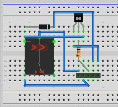
This is using a 5V relay capable of switching a couple amps of current, all driven by a low current output pin on a chip with an NPN resistor. The diode across the relay is standard and this is sometimes called a flyback diode. When the mechanical relay opens and closes there can be a large voltage spike and the diode will help isolate that to where it doesn't belong.
Parts
| Amount | Part Type | Properties |
|---|---|---|
| 1 | Generic female header - 5 pins | row single; hole size 1.0mm,0.508mm; pin spacing 0.1in (2.54mm); package THT; pins 5; form ? (female) |
| 1 | Rectifier Diode | package 300 mil [THT]; type Rectifier; part # 1N4001 |
| 1 | NPN-Transistor | package TO92 [THT]; type NPN (EBC) |
| 1 | 10k? Resistor | tolerance ±5%; bands 4; resistance 10k?; pin spacing 400 mil; package THT |
| 1 | Relay T73 | voltage 5V |
With it laid out on the breadboard, it looks something like this.

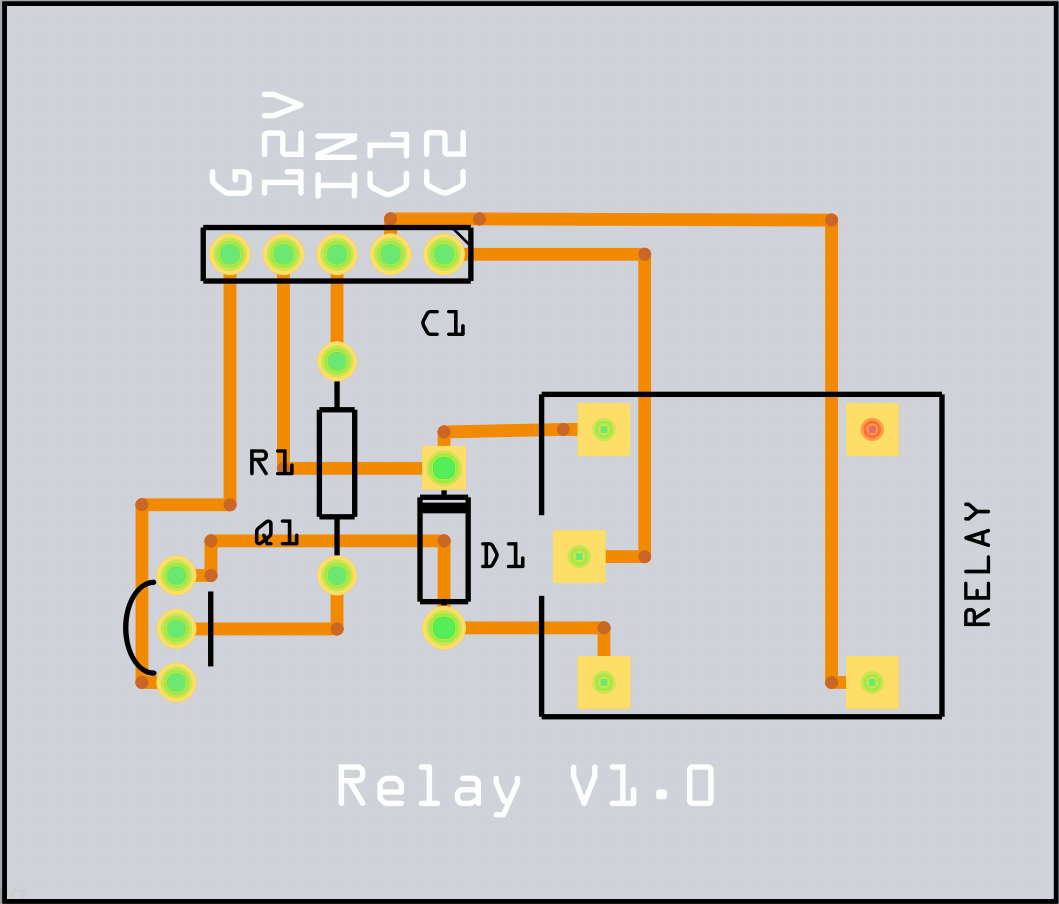
Then, with it on the PCB, it looks something like this.

Download relay_board.fzz and open it up in Fritzing if you want to work with it yourself or etch one.
